Difference between revisions of "Temperature Difference Sensor and Switch for Solar Water Circulation Pump"
(Circuit diagram of temperature differentials for switch) |
m (a note about good hysteresis for the pump) |
||
| Line 5: | Line 5: | ||
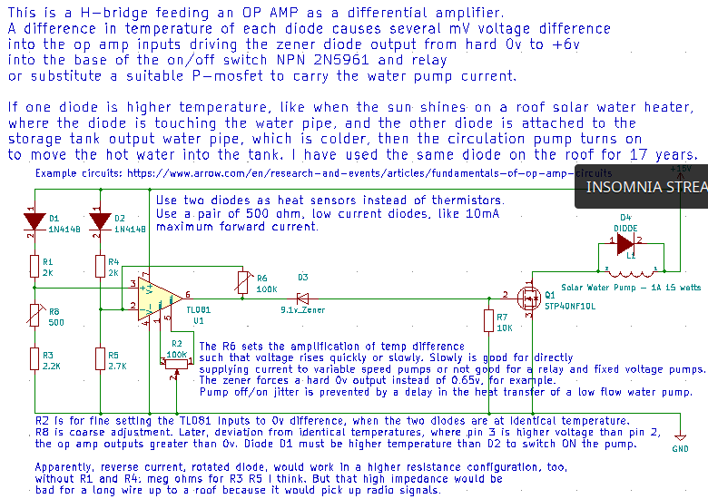
[[File:Water_temp_difference_sensor_and-on-off-switch_for_solar-pump.png]] | [[File:Water_temp_difference_sensor_and-on-off-switch_for_solar-pump.png]] | ||
| + | |||
| + | There is hysteresis because the copper pipes transfer heat and cool with a lag to the pump switching off/on. | ||
| + | Also, my pump can run without harm, at low voltages, and slower speed. So a sharp slope in the switching speed versus temperature change | ||
| + | is not needed for my pump. A steeper slope and instantaneous off/on for some other pump might need some further thought, like perhaps | ||
| + | feedback-R6 should be much larger or omitted completely for more amplification. Experiment with it. | ||
Revision as of 06:42, 7 May 2022
ALL MY PROJECTS ARE HERE: https://opencircuits.com/index.php?title=User:Definitionofis
This is using two diodes to sense the temperature of the roof solar collector and the storage tank in the house. The diodes form a H-bridge which drifts +- through to -+ across the op amp inputs, depending on the temperature difference which varies the diodes' forward resistance. I have been running this for seventeen years with the diode on the roof touching the hot water outlet pipe.
There is hysteresis because the copper pipes transfer heat and cool with a lag to the pump switching off/on. Also, my pump can run without harm, at low voltages, and slower speed. So a sharp slope in the switching speed versus temperature change is not needed for my pump. A steeper slope and instantaneous off/on for some other pump might need some further thought, like perhaps feedback-R6 should be much larger or omitted completely for more amplification. Experiment with it.
