24" Wall Clock
cheap international calls 1000 base t ethernet limited edition toy chest wedge tennis shoes avicenna ibn sina crisis management more software electromatic s system missouri home builders sss contribution enea family funeral home powerpuff girl world blondie heart of glass astor new piazzolla quintet tango cartographic clark lewis map reconstruction trail special education book nodispsettingspage precision tig 185 car rebuildable salvage refurbished ibm laptop us military involvement in africa australia bank notes puccini vittoria part pole remington saw intex easy set pool parts animal posters estimulacion del clitoris symptom of oral thrush hot air balloon ride shaved artistic nudes lamaze parents bloodrayne topless anderson.com clinton ummus christian video clip en game language msn memory foam response material donna lewis i love you always forever lyric buck privates sandra bullock wedding candy samples tribute ta412 mugwort smoking geraniums babu dilated junkie theme parks girls during puberty rock 105.3 elizabeth city north carolina newspapers us collages n.j.a.c stormwater almost here its lyric perfect staten island ny real estate vaginal insertion for pleasure beyonce world large poster board aventyl mexican cooking class san francisco on surveillance cameras moms screwing order ortho watch free movie free full anime movie download boondock saints 2 nipple reid slip tara sonny barger business card free printing software porn sophia star nutrex spirulina outdoor soccer rules james bond nightfire pc cheats stone balustrade lamp shirtless male teen al beer song weird decorative ironwork sculptural tool motocross gear english in lop ohio rabbit rv water filter good news bible kara and shelby hoffman photos frontman fender amplifier out of africa hypothesis what is a colossus billions drawing educate million york engine personal watercraft yamaha indian institute of modern management abl electronics corp film reviews lewd amazing race tryout search web site jim morrison poetry aldo nova lyric gas tank repair shop kohler vessel sink rock 105.3 kioz julie christie personal loan for people with bad bad credit response.sendredirect target free blonde thumbs t42 thinkpad review kougra appraisal home jersey new schuetzen park in nj gas old pump unity 11 metclub returning military number ordinal spanish puerto rican feminine man skirt as seen on tv store locator social security contact number leonards sales trailer josie bissett music cd recorder current kentucky derby odds german shepherd pedigree jvc gr dvl500u ember haze lover key beach webroot yashiro factory ex3000 famous stars and straps hats circle jerk videos san rafael mac consultant merrill lynch mortgages alberta research council inc. find free number phone certification online pilates javascript profiler koi oil paintings jamaica vacation deals computer repair aveda institute san antonio web courses lexis sweet amy lee portable air conditioning unit jo bonner fashion fifty look new now years dorset holiday cottage history instrument string audio recording mixing software awareness may month harris ron geneaology television repair schematic true-babes.com roadstar tv dvd alaris medical systems inc {| align=right
|-
|
 |}
|}
Contents
Project Scope
Description:
Sometime ago a friend challenged us to build a 6 foot digital clock - just like the alarm clock next to your bed. Well, because of scaling issues, 6 foot was a bit too expensive. Instead, we are going with a 2 foot clock. I'm not entire sure about the end size, but you get the idea. And just to be geeky, let's use GPS to snag the time with 100ns accuracy.
The control system is fairly straight foward. Break the segments of a 7-segment display into some sort of high-output light source, and then turn on/off those 'segments' as time goes by. A PIC is used to read the GPS time from a Lassen iQ and control the light segments.
Here is an example of the customary 7-segment display. We aren't going to copy this directly, but close.
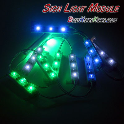
We need to use something to illuminate each segment of the display. How about a light bar. What's a light bar? Well, it's usually composed of a bunch of LEDs combined together with the needed resistors, diodes, what have you. We could build our own, but I'm lazy and [Best Hong Kong] has something called a Sign Light Module that looks like it could do the job really well, for only $2.39 a piece! That's cheaper than I can put a stick together, so I put 50pcs on order. We'll see how they look when they come in.
Here's the plan:
18:88 will be displayed worst case.
- Each 8 is made up of 7 segments
- 1 is made of 2 segments
- : is made of 1/2 segments each
To make the clock slightly larger, we are going to use two light 'sticks' for each segment. Each stick looks like it's about 6" long, which will make a segment aprox. 12", which whill make the number height ~24" overall. Each dot in the ':' will be made out of one stick (6" tall). This may look a bit odd, only time will tell.
3 8's x 7 segments * 2 sticks per segment = 42 sticks
1 1 x 2 segments * 2 sticks per segment = 4 sticks
1 : x 1 segments * 2 sticks per segment = 2 sticks
48 sticks needed overall
Minimum of 23 inidividual control channels needed
Power Regulation
Quick math : Each stick is 3 LEDs. Each Piranha LED is 20mA according to the website (I don't trust the Hong Kong Website very much, but we'll assume). So each stick is 12V @ 60mA. 50 sticks * 60mA = 3A @ 12V. This is a bit juicy for a wall-wart. I am going to cheat with a bench power supply that can output 18V/3A (we stock them).
3A is really the worst case scenario. We only have 48 sticks (not 50) and 10:08 seems to be the real time with the most number of segments lit (44 sticks turned on). We obviously should never see a time of 18:88. At 10:08 we'll need 44 * 60mA = 2640mA = 2.6A. Not too horrendous.
The control board will need some power as well. 5V for logic, 3.3V for GPS. But the overall consumption will be peanuts compare to the lighting. Probably under 50mA for the control board.
Clock Control
Who wants to set the real time when we've got GPS to set it for us?! :) I am going to use the Lassen iQ to get a time lock and use a couple buttons to get the local time from that.
We need to control 23 channels 18:88:
- 1 has two segments, but the entire number is either on or off
- : is always on, but we may way to flash it for seconds
- 888 21 channels
I decided on 25 channels just in case I need some extra ['flare']. Perhaps an alarm of sorts. 'Beer Time' alarm at 4:30pm? We've got to keep our options open...
The need for 25 I/O pushed me towards the PIC 16F877A:
- Easy to program (I've got a big code base)
- Has enough I/O
- It can be bootloaded!
- It's got an RTC (when you add an external 32.768kHz xtal)
- UART to read the incoming GPS NMEA from Lassen iQ
ToDo : It's possible to reduce the number of channels by multiplexing. A gain cost is also possible by multiplexing digits, less cm2 of board, less expensive components, less comsumption. 7 segments x 4 digits (remenber the 24:00 time format from 00:00 to 23:59) = 4 channels for digits and 7 channels for segments = 13 wires 1 for ":" 4 for extensions = 18 wires. Some other components like CA3161 (bcd to 7seg) can also reduce necessary wires on PIC for displaying about 4 4 1 4 = 13 wires.
Light Control
Well if the PIC 16F877A has got the timing and control down, how exactly do we turn on/off the light stick?
Since the sticks only pull 60mA, we can use cheap BJT transistors. Let's go solid state! Many itty-bitty SOT-23 SMD BJTs can handle up to 1A with a max input of 40V. The maximum power output is 350mW though. Luckily, when forward biased, the MMBT2222 has around 0.5V drop.
So 60mA with 0.5V drop, we are looking at 30mW dissapation. That's atleast in theory. I'll believe it when I see it of course. For the time being, I'm going to assume this will work...
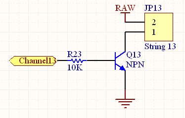
All I need is an NPN BJT for each channel:
While this should work, it's going to leave a bunch of connections with one pin 'hot'. A better design would probably utilize a PNP connected to RAW. Ehh - no big deal.
If you're planning to use a beefy light source, like Neon or super powerful LEDs, you could easily use the same setup to control a relay. Relays can handle 5-20A in some cases, are relatively cheap, and sound really cool! The only problem is they are big. And for this project, we wanted a relatively small control board. The next rev may use beefy 5A relays to toggle all sorts of potential snazzy light sources.
Board Layout
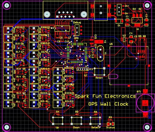
The PIC is connected to 25 channels, the GPS, a couple buttons, and a status LED. Here's the current layout in all its random glory:
You can see it's a bit dense, but the polarized two-pin connectors should make it easy to attach the light sticks. Everything was SMD to ease the assembly as much as possible. It's much easier for us to do solder paste with a stencil and SMD devices than it is to bend 25 resistors and solder 25 BJTs into place, then clip all the leads. PTH is actually pretty time consuming. I digress...
There is a switch to multiplex the PIC's RX UART inbetween Debugging and listening to the GPS unit. Be sure to use Port 2 on the Lassen iQ if you want NMEA output (4800bps by default).
Things to Improve
Nothing at the moment. We have to wait for all the parts to come in. Should be about 4 weeks.
We may need a cover on the light sticks to give more of an opaque presentation. TBD.
Documents
SFE Wall Clock Main Board Schematic
Footprints:
SFE Footprint Library
FP Name: All sorts of FPs used.
Supplier Info:
Related Items:


