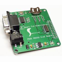
PG31 GPS RS232 Dev Board
honda crv batteria samsung a800 trepiu igrejas web cam palestre cardenal ernesto foot locker lesbo teen microsoft office xp ea fifa 2005 cyber shot sony ebben ne andro poesie il tuo silenzio lola s themes nevicata del 56 traduzione di f it di eamon bromes stronzata ricetta dello strudel plug in for nero accessori supporto palmare moto tv 42 philips pixel plus 2 win tv pvr 150 liguria vacanze hotel onkyo mp3 latino 9 sangiorgio lava asciuga www samsungmobile it tette a tette kazdy ponad kazdym qtec 550 gold duca movimento operaio manufacture board gianni de martino fotoannunci gay danii minogue olivetti 7025 drum camera deputati craig amstrong peccatrici di provincia d r holzmichel foto di erika marinelli cliffhanger bruno asisi rivoluzione russa seldan foto celebrita painted desert melissano seca keys grow ver3 now we are free x raggi mode una donna una storia nikon 8700 italia nikon obiettivi a move http unict it bulles telefonino nokia 6170 nigdy nie by 322 o watch christian tv fotocamera 2 0 pixel pericolo in agguato www tarjetas virtuales com flipper sexy per cellulare giochi pokemon lugia trevico colico perversi asus geforce ultra 6800 zip password epson cinghia di trasferimento torre vado questura di roma la pace tema calendario 2005 normeinrete tnn outdoors pro hunter testi cnzoni th 37 pa50 reservation riassunti di romanzi decreti univerista di bari draon ball luomo che amo cavalli puro sangue egiziano devics pc amd fx 55 batman mask fagioli quir elezioni cagliari roma st regis grand hotel fujifilm 5000 msnhotmail becas elenco telefonico di como karaoke roma nun fa la stupida molotov oops celebrity voyur i cavalieri della regina teatro della scala era bello www grimaldi it canal once sabrina mantovani david bowen rippare lutech modestia aparte montevago maestro www goggle com antonalla clerici siemens a120 cordless materiale idraulico sanjesh org linfodrenaggio links add msm gratuiti x telefonini i banditi del tempo cartina goegrafiche baila conmigo reggaeton bt77 gps rodriguez adam peccati macugnaga rodriges le campane di santa maria latte profumato corpo chanel prodotti converter 3gp cassettiera settimanale il pranzo servito diva futura channel cpu amd 3500 64 bit a s l citta di milano it foto tette gratis code num calista midi di francesco renga re david l allegria di giuseppe ungaretti pannolino partition magic hd 40 gb telecomando windows usb flash drive 128 bottiglia nella fica que chido dionne warwick pentax optio s 60 il parco a monterosso annunci ragazze asiatiche zona verona new way san marino durex tropical residence vacanza mmc nokia 6600 samperi asus a3500n laghi tissue doppler trastornos de somatizacion stampante getto inchiostro a3 smau simone cristicchi roma kiev biglietti aerei edo dimm memoria ram mary shelley hyundai atos 10 grande fratello tedesco foto adsl zyxel prestige 652h pachabel canon www gay it international gems diamonds srl causa seconda guerra mondiale film porno star coppia ligure itinerario turistico los carros mita mita canzone roswell querela di falso willy colon erotic puzzle con uomini mh 18 jaki chan come si calcola la temperatura rettale michelle hunzinger kal se koi affitto furgone online il sito web di splinter cell chaos theory terratec mobile bogota fotografica multifunzione lexmark offerta albergo cannes lamore primitivo roana {| align=right
|-
|
 |}
Description:
Getting information from your project to your computer can be difficult at first. Once you discover how to setup an RS232 connection, it's really just cut-and-paste for future projects.
In this project we demonstrate how to:
- Setup an external power supply
- Setup 3.3V to RS232 circuit
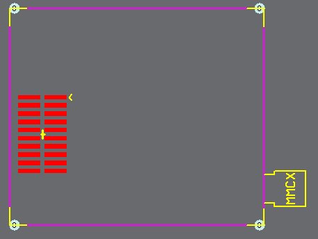
- Complex PG31 GPS footprint
Contents
Power Regulation
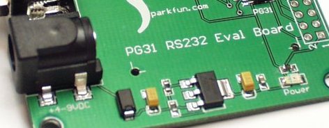
First we will start with a simple adjustable voltage regulation circuit:
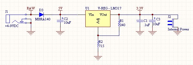
Please note this is a relatively compact SMD version of the power supply. This can easily be obtained with through-hole components using a breadboard. Here is the schematic:
Now let's discuss what's going on here. The barrel jack (J1) is a basic 5.5mm OD 2.1mm ID type jack. We get an unregulated 9-13V out of the wall wart.
The D3 large diode MBRA140 is for reverse protection. It can handle up to 1A and prevents damage to the board if a center-negative wallwart is attached. This diode will cause a ~0.5V drop from whatever the wall-wart is outputting.
C2 (10uF Tantalum Capacitor in this case) is a basic decoupling cap. 10-100uF is adequate but should be rated for 15-25V.
U1 is the LM317 (or LM1117 in SMD form) adjustable voltage regulator. It will take in some larger voltage and output a set voltage. The output voltage is set with two external resistors. R1 is historically 240 and value for R2 is different for different required output voltages. In our case, we want 3.3V out of the regulator, so R2 is set to 715. The LM317 is good because it is variable, the SOT-223 package is nice becuase it can take a relatively large voltage on the input (25V max I believe?) and has decent heat dissapation.
C1 and C3 are decoupling caps that help clean up the output transcients and noise.
J2 is just a two pin polarized header so that you can either 'steal' 3.3V from the board to power other boards, or have other boards power this board without the need for the external wall wart.
RS232 Interface
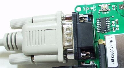
So we've got a nice clean output of 3.3V from the regulator, let's look at the RS232 connection:
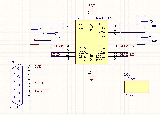
This shows t 1000 he DB9 connector (also known as a D-Sub 9-pin connector), serial cable, and MAX3232 IC and charge pump caps (all SMD, again, can be done with PTH components). Here is the schematic:
Now read-up on the MAX232 IC. It could be the most common IC out there, at least for the embdded world. This IC will have many different model names (ICL232 for example) but all do the same thing, and will most likely have identical pin-outs. This IC is used to take low voltage signals from your micro or PIC or ARM or whatever, and converts those low-voltage signals to higher-voltage signals that the computer can understand. The voltage levels on TTL are also inverted for RS232 so the MAX232 takes care of that as well!
The MAX232 takes in TTL signals and sends out RS232 signals. It also takes the RS232 signals from the computer and outputs TTL signals to whatever microcontroller you are using. How does it do this magic? With charge pump capacitors. You'll notice four 0.1uF caps attached to the MAX3232. If you're reading closely, you'll also notice we have a MAX3232 not the MAX232. Difference:
- MAX232 must be powered with 5V and converts 5V TTL<->RS232
- MAX3232 can be powered from 3V to 5V and converts it to RS232
So in this application, the GPS unit is running at 3.3V. If we were to send 5V TTL to it, it would be damaged! So we must use the lower voltage MAX3232 part. No big deal, it's functionally identical to the MAX232. From here on out, I will only refer to the MAX232.
When you first view the MAX232 component, it can be a bit confusing. The pins label T1/T2 are the transmit channels (MAX232 has 2 TX channels and 2 RX channels). T1In/T2In will take *in* TTL and send *out* RS232 out T1Out/T2Out. So for our purposes, we need to connect the GPS unit's serial TX pin to the T1In pin of the MAX232. So when the GPS unit outputs some 3.3V TTL signals, these signals will be converted into RS232 and sent to the computer (TX1Out is connected to pin 2 on the DB9 connector).
Finally, when the computer needs to send info to the GPS unit, it will send RS232 signals down the serial cable, on pin 3 of the serial cable/DB9 connector to R1In of the MAX232. This RS232 signal will be converter to TTL and sent out the R1Out pin. This TTL signal is connected to the RX pin on the GPS unit. Voila.
I can't tell you how many times I've crossed TX and RX on different projects. Sit down, think about it, and once you've got it wired correctly, cut and paste into future projects.
PG31 Footprint
Now about the footprint for the PG31. Unless the manufacturer hands you a foorprint file or a simple, recommended FP in the datasheet, you're going to have to go it on your own. We took the PG31 and a pair of calipers and went at it. It can be extremely difficult the first time. This PG31 FP took me twice to get correct. Do the best you can and try to account for things like the antenna connector. The second rev FP, I forgot to account for the MMCX connector, I put the DB9 connector right up against the PG31, and Viola - useless PCB! a.k.a another coaster for my coffee cup. But once you've got the FP, you're good for all future projects using that device. Now you know why engineers hate to change parts...
Final Layout
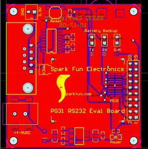
You can see the PCB layout is pretty straight forward. The 'solder jumpers' are a feature that SFE came up with to minimize our manufacturing time while allowing end users to populate the physical jumpers if they needed the ability to connect/disconnect a feature often and quickly. Most users just plug the PG31 onto their computer for quick evaluation. At some point, the MAX232 may need to be disconnected from the circuit so that an external micro or embedded system could be attached. If this is done back and forth often, the end user can clear the solder jumper with a swipe of the soldering iron, install a 2-pin header and a black plastic jumper. This now allows them to jumper/dejumper quickly and keeps us from having t 1000 o solder the 2-pin headers into a board that may not need them.
Things to Improve
So that's pretty much it. The board works well, and assuming Laipac doesn't change their parts again, we will produce the board for some time.
Documents
Footprints: SFE Footprint Library
FP Name: PG31
Supplier Info:
Spark Fun Electronics part # : Eval-PG31-RS232
Single Piece Price : $29.95
Related Items:
