Difference between revisions of "Minimig Video d/a resistor ladder"
Jump to navigation
Jump to search
(simulation results) |
(→Useful links: component source) |
||
| (4 intermediate revisions by the same user not shown) | |||
| Line 1: | Line 1: | ||
| − | + | == Electrical model == | |
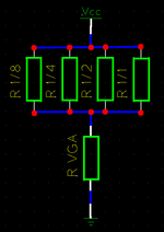
[[Image:Minimig_dac_resistor_ladder_model.png|thumb| none |150px|D/A resistor ladder electrical model]]<br><!-- http://en.wikipedia.org/wiki/Wikipedia:Extended_image_syntax --> | [[Image:Minimig_dac_resistor_ladder_model.png|thumb| none |150px|D/A resistor ladder electrical model]]<br><!-- http://en.wikipedia.org/wiki/Wikipedia:Extended_image_syntax --> | ||
| − | Equations | + | == Equations == |
:Defining constants: | :Defining constants: | ||
::U_vga = 0.7 V | ::U_vga = 0.7 V | ||
| Line 10: | Line 10: | ||
::Total resistance = 1/(1/4000+1/2000+1/1000+1/560)+75 = 357.8282.. Ω | ::Total resistance = 1/(1/4000+1/2000+1/1000+1/560)+75 = 357.8282.. Ω | ||
::Common current through resistor ladder plus vga impedance (75Ω) = 3.3V / 357.8282.. = 0.009222 A | ::Common current through resistor ladder plus vga impedance (75Ω) = 3.3V / 357.8282.. = 0.009222 A | ||
| − | ::Current * [[Video Graphics Array|VGA]] impedance = 0. | + | ::Current * [[Video Graphics Array|VGA]] impedance = 0.6917 V (specification says max 0.7V p-p) |
| − | ::Output voltage = 75 * (3.3/(1/(1/4000+1/2000+1/1000+1/560)+75)) = 0. | + | ::Output voltage = 75 * (3.3/(1/(1/4000+1/2000+1/1000+1/560)+75)) = 0.6917 V |
:Simplification: | :Simplification: | ||
| Line 17: | Line 17: | ||
:Base resistor value = (1/8+1/4+1/2+1/1)/(1/((R_vga*U_vcc)/U_vga-R_vga)) = 522.3214Ω | :Base resistor value = (1/8+1/4+1/2+1/1)/(1/((R_vga*U_vcc)/U_vga-R_vga)) = 522.3214Ω | ||
| − | + | ||
:Deviation summary: | :Deviation summary: | ||
::0523/523 = 1.0000 | ::0523/523 = 1.0000 | ||
| Line 27: | Line 27: | ||
:Maximum output voltage if VGA impedance is 75Ω is: (75*3.3)/(1/(1/4220+1/2100+1/1050+1/523)+75) = 0.6981 V | :Maximum output voltage if VGA impedance is 75Ω is: (75*3.3)/(1/(1/4220+1/2100+1/1050+1/523)+75) = 0.6981 V | ||
| − | Useful links | + | == Useful links == |
:[http://en.wikipedia.org/wiki/Resistor Wikipedia: Resistor] | :[http://en.wikipedia.org/wiki/Resistor Wikipedia: Resistor] | ||
:[http://en.wikipedia.org/wiki/Preferred_number#Capacitors_and_resistors Wikipedia: Preferred number] | :[http://en.wikipedia.org/wiki/Preferred_number#Capacitors_and_resistors Wikipedia: Preferred number] | ||
:[http://www.digikey.com/scripts/DkSearch/dksus.dll?Cat=65538;keywords=resistor Digikey: Resistors] | :[http://www.digikey.com/scripts/DkSearch/dksus.dll?Cat=65538;keywords=resistor Digikey: Resistors] | ||
| + | :[http://en.wikipedia.org/wiki/Resistor#Thick_and_thin_film Wikipedia: Thin vs Thickfilm resistor] | ||
| + | ::In essence Thin = More expensive, but without nasty temperature coefficient. | ||
| + | |||
| + | Digikey ordering:<br> | ||
| + | {| class="wikitable" | ||
| + | |- | ||
| + | ! Value !! Order number (digikey.com) | ||
| + | |- | ||
| + | | 523 || RR12P523DCT-ND | ||
| + | |- | ||
| + | | 1.05K || RG20P1.05KBCT-ND | ||
| + | |- | ||
| + | | 2.1K || RR12P2.1KDCT-ND | ||
| + | |- | ||
| + | | 4.22K || RR12P4.22KBCT-ND | ||
| + | |} | ||
| − | [[Image:Minimig_v1.0_video_dac_resistor_ladder_simulation_original.png|thumb| right |250px|Value vs output | + | == Value-vs-Amplitude Originaly == |
| − | The original 4000Ω 2000Ω 1000Ω 560Ω resistors, Gives this curve for desired vs actual | + | [[Image:Minimig_v1.0_video_dac_resistor_ladder_simulation_original.png|thumb| right |250px|Value vs output amplitude originaly]]<br> |
| + | The original 4000Ω 2000Ω 1000Ω 560Ω resistors, Gives this curve for the desired vs actual amplitude:<br> | ||
Note the dent in the middle of the curve!<br> | Note the dent in the middle of the curve!<br> | ||
| − | < | + | <!-- awk '{print "|-\n| "$1" || "$2}' da_org.txt --> |
| − | 0 0.000002 | + | {| class="wikitable" |
| − | 1 0.060736 | + | |- |
| − | 2 0.119277 | + | ! Value !! Amplitude [V] |
| − | 3 0.175740 | + | |- |
| − | 4 0.230233 | + | | 0 || 0.000002 |
| − | 5 0.282857 | + | |- |
| − | 6 0.333708 | + | | 1 || 0.060736 |
| − | 7 0.382873 | + | |- |
| − | 8 0.389764 | + | | 2 || 0.119277 |
| − | 9 0.437103 | + | |- |
| − | 10 0.482927 | + | | 3 || 0.175740 |
| − | 11 0.527307 | + | |- |
| − | 12 0.570310 | + | | 4 || 0.230233 |
| − | 13 0.612000 | + | |- |
| − | 14 0.652436 | + | | 5 || 0.282857 |
| − | 15 0.691673 | + | |- |
| − | < | + | | 6 || 0.333708 |
| + | |- | ||
| + | | 7 || 0.382873 | ||
| + | |- | ||
| + | | 8 || 0.389764 | ||
| + | |- | ||
| + | | 9 || 0.437103 | ||
| + | |- | ||
| + | | 10 || 0.482927 | ||
| + | |- | ||
| + | | 11 || 0.527307 | ||
| + | |- | ||
| + | | 12 || 0.570310 | ||
| + | |- | ||
| + | | 13 || 0.612000 | ||
| + | |- | ||
| + | | 14 || 0.652436 | ||
| + | |- | ||
| + | | 15 || 0.691673 | ||
| + | |} | ||
| + | |||
| + | == Value-vs-Amplitude Modified == | ||
| + | [[Image:Minimig_v1.0_video_dac_resistor_ladder_simulation_modified.png|thumb| right |250px|Value vs output amplitude modified]]<br> | ||
| + | The modification with 4220Ω 2100Ω 1050Ω 523Ω resistors, Gives this curve for the desired vs actual amplitude:<br> | ||
| + | {| class="wikitable" | ||
| + | |- | ||
| + | ! Value !! Amplitude [V] | ||
| + | |- | ||
| + | | 0 || 0.000002 | ||
| + | |- | ||
| + | | 1 || 0.057625 | ||
| + | |- | ||
| + | | 2 || 0.113793 | ||
| + | |- | ||
| + | | 3 || 0.167545 | ||
| + | |- | ||
| + | | 4 || 0.220000 | ||
| + | |- | ||
| + | | 5 || 0.270256 | ||
| + | |- | ||
| + | | 6 || 0.319355 | ||
| + | |- | ||
| + | | 7 || 0.366446 | ||
| + | |- | ||
| + | | 8 || 0.413880 | ||
| + | |- | ||
| + | | 9 || 0.458053 | ||
| + | |- | ||
| + | | 10 || 0.501297 | ||
| + | |- | ||
| + | | 11 || 0.542855 | ||
| + | |- | ||
| + | | 12 || 0.583575 | ||
| + | |- | ||
| + | | 13 || 0.622742 | ||
| + | |- | ||
| + | | 14 || 0.661153 | ||
| + | |- | ||
| + | | 15 || 0.698131 | ||
| + | |} | ||
| − | + | == Gnuplot == | |
| − | + | Gnuplot command: | |
| − | + | :<pre>gnuplot> plot "dac_sim.txt" using ($1):($2) smooth csplines</pre> | |
| − | |||
| − | 1 | ||
| − | 2 | ||
| − | |||
| − | |||
| − | |||
| − | |||
| − | |||
| − | |||
| − | |||
| − | |||
| − | |||
| − | |||
| − | |||
| − | |||
| − | |||
| − | </pre> | ||
| + | == Simulation script == | ||
| + | <br> | ||
Simulation program (perl):<br> | Simulation program (perl):<br> | ||
<pre> | <pre> | ||
| Line 121: | Line 182: | ||
#----------------------------------------------------------------------------- | #----------------------------------------------------------------------------- | ||
</pre> | </pre> | ||
| − | |||
| − | |||
Latest revision as of 17:50, 28 August 2007
Contents
Electrical model
Equations
- Defining constants:
- U_vga = 0.7 V
- R_vga = 75 Ω
- U_vcc = 3.3 V
- Total resistance = 1/(1/4000+1/2000+1/1000+1/560)+75 = 357.8282.. Ω
- Common current through resistor ladder plus vga impedance (75Ω) = 3.3V / 357.8282.. = 0.009222 A
- Current * VGA impedance = 0.6917 V (specification says max 0.7V p-p)
- Output voltage = 75 * (3.3/(1/(1/4000+1/2000+1/1000+1/560)+75)) = 0.6917 V
- Simplification:
- U = (75*3.3)/(1/(1/4000+1/2000+1/1000+1/560)+75) = 0.6917V
- Base resistor value = (1/8+1/4+1/2+1/1)/(1/((R_vga*U_vcc)/U_vga-R_vga)) = 522.3214Ω
- Deviation summary:
- 0523/523 = 1.0000
- 1050/523 = 2.0076
- 2100/523 = 4.0153
- 4220/523 = 8.0688
- As can be seen no more than 1% is useful with digikey resistors. Resistor combinations will add tolerances and use valuable pcb space.
- Maximum output voltage if VGA impedance is 75Ω is: (75*3.3)/(1/(1/4220+1/2100+1/1050+1/523)+75) = 0.6981 V
Useful links
- Wikipedia: Resistor
- Wikipedia: Preferred number
- Digikey: Resistors
- Wikipedia: Thin vs Thickfilm resistor
- In essence Thin = More expensive, but without nasty temperature coefficient.
Digikey ordering:
| Value | Order number (digikey.com) |
|---|---|
| 523 | RR12P523DCT-ND |
| 1.05K | RG20P1.05KBCT-ND |
| 2.1K | RR12P2.1KDCT-ND |
| 4.22K | RR12P4.22KBCT-ND |
Value-vs-Amplitude Originaly
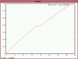
The original 4000Ω 2000Ω 1000Ω 560Ω resistors, Gives this curve for the desired vs actual amplitude:
Note the dent in the middle of the curve!
| Value | Amplitude [V] |
|---|---|
| 0 | 0.000002 |
| 1 | 0.060736 |
| 2 | 0.119277 |
| 3 | 0.175740 |
| 4 | 0.230233 |
| 5 | 0.282857 |
| 6 | 0.333708 |
| 7 | 0.382873 |
| 8 | 0.389764 |
| 9 | 0.437103 |
| 10 | 0.482927 |
| 11 | 0.527307 |
| 12 | 0.570310 |
| 13 | 0.612000 |
| 14 | 0.652436 |
| 15 | 0.691673 |
Value-vs-Amplitude Modified
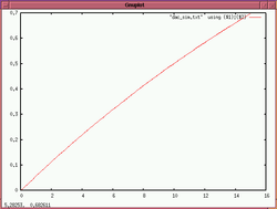
The modification with 4220Ω 2100Ω 1050Ω 523Ω resistors, Gives this curve for the desired vs actual amplitude:
| Value | Amplitude [V] |
|---|---|
| 0 | 0.000002 |
| 1 | 0.057625 |
| 2 | 0.113793 |
| 3 | 0.167545 |
| 4 | 0.220000 |
| 5 | 0.270256 |
| 6 | 0.319355 |
| 7 | 0.366446 |
| 8 | 0.413880 |
| 9 | 0.458053 |
| 10 | 0.501297 |
| 11 | 0.542855 |
| 12 | 0.583575 |
| 13 | 0.622742 |
| 14 | 0.661153 |
| 15 | 0.698131 |
Gnuplot
Gnuplot command:
gnuplot> plot "dac_sim.txt" using ($1):($2) smooth csplines
Simulation script
Simulation program (perl):
#!/usr/bin/perl
#
# Created:  2007-08-23 05:25.32
# Purpose:  Minimig Video D/A resistor ladder simulation
#-----------------------------------------------------------------------------
$map[$n++]=0;
$map[$n++]=8;
$map[$n++]=4;
$map[$n++]=12;
$map[$n++]=2;
$map[$n++]=10;
$map[$n++]=6;
$map[$n++]=14;
$map[$n++]=1;
$map[$n++]=9;
$map[$n++]=5;
$map[$n++]=13;
$map[$n++]=3;
$map[$n++]=11;
$map[$n++]=7;
$map[$n++]=15;

for($v=0; $v<=15; $v++) {
  $d=$map[$v];

  $d3 = ($d & 8)?1:0;
  $d2 = ($d & 4)?1:0;
  $d1 = ($d & 2)?1:0;
  $d0 = ($d & 1)?1:0;

  if(  !($d3==0 && $d2==0 && $d1==0 && $d0==0)   ) {
    $r_dac=1/(
#      ${d3}/4000+ ${d2}/2000+ ${d1}/1000+ ${d0}/560
      ${d3}/4220+ ${d2}/2100+ ${d1}/1050+ ${d0}/523
      );
    } else { $r_dac=100*1000*1000; }

  $u = (75*3.3)/($r_dac+75);

  printf("%d %f\n",$v,$u);
  }

#-----------------------------------------------------------------------------


