Difference between revisions of "Linuxstamp II 8-channel RC Control board"
Linuxvolts (talk | contribs) |
Linuxvolts (talk | contribs) |
||
| Line 6: | Line 6: | ||
== Status == | == Status == | ||
| − | You can get a board from [http://www.thelinuxstamp.com/shop/article_10/8-channel-RC-control-board. | + | You can get a board from [http://www.thelinuxstamp.com/shop/article_10/8-channel-RC-control-board.html thelinuxstamp.com]. |
== Power supply == | == Power supply == | ||
Latest revision as of 22:48, 23 February 2011
Contents
Description
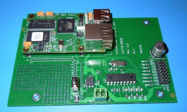
This board can control up to 8 RC servos via the onboard Pololu chip. A simple serial line from the Linuxstamp II controls the Pololu chip. There is also a prototyping area with access to power as well as UART, SPI, I2C & GPIO lines from the Linuxstamp II.
Status
You can get a board from thelinuxstamp.com.
Power supply
There are two options for the poser supply. Most of the time a 1.5A linear regulator from ST should be fine (digikey p/n 497-3468-1-ND). However if more current is needed a switching power supply from Recom can be used (digikey p/n 945-1028-ND).
License
All files for this project are licensed under the GNU GPL V2
Hardware design files
Warning!!! Use this design at your own risk. You can find the design files here.
Demo programs
There are 2 demo programs that can be found here.
Mounting
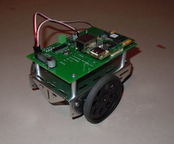
The mounting holes on the board are designed to match the boebot Chassis. So the board can be used with continuous rotation servos to make a little rover.

